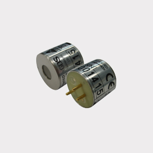
Prime sensor setup

Set up
Power Supply
15 to 30Vdc 24v nominal
Outputs
3 wire 4~20mA / 4 wire CANbus
Relays Low alarm SPCO
(when High alarm SPCO 0-5A @ 30Vdc
fitted) Fault alarm SPCO
Inhibit option during servicing
Logging Intervals - variable time
Roll over/stop
Storage - 2,880 readings
Requires RS232 lead
PC or laptop (dedicated)
Hyperterminal (download from GDS website)
Set up procedure:
New sensors are supplied ready to connect to the system. The following procedure is for full set up and where the sensor cell has been replaced - only sections 5, 6, 7, 9 and 11 need to be carried out. Voltage measurements are made wrt AG unless otherwise specified.
1. Insert jumpers J20 and J6 position SO for 4-20mA source output.
2. Turn sensor voltage potentiometer anti-clockwise (minimum voltage).
3. Connect sensor to J2 terminal W-white Y-yellow P-pink.
4. Connect 24V + and 0V to JP10, short the 4~20mA terminal by inserting test link at J9.
5. Measure the sensor voltage at SV and adjust by turning sensor volts pot for the correct reading 3.5v DC.
DO NOT EXCEED THE REQUIRED VOLTAGE OTHERWISE PERMANENT DAMAGE WILL OCCUR.
6. Rotate 20mA pot fully anti-clockwise (minimum span).
7. When in clean air the sensor bridge is zeroed by adjusting zero pot until the dual colour LED D1 is off.
8. Connect PC hyper terminal using RS232 Combi adaptor (part no. 160-510 and lead part no. 160-515) at 4800 baud connected to J3 and initialise the sensor using (C) calibration mode, then shift + ($) command from the keyboard.
9. Using a digital mV meter measure across test pins TP8/9 and adjust 4mA pot for 4mA (zero) = 4mV
10. Then press (Z) on the PC to zero the reading.
11. Apply a known test gas to the sensor (50% F.S.D.) for 1 minute at a flow rate of 1 litre to give a 12mA = 12mV across test pins TP8/9, adjust 20mA pot for correct mV reading.
12. When using a PC press (S) to enter span mode and using (H) or (L) adjust for the correct reading.
13. Press (space) to exit span and then (X) to exit the calibration mode.