THQ Series

THQ Series
The THQ Series capacitor shall utilize sintered tantalum anodes and ruthenium oxide coated cathodes operating in aqueous electrolyte with additives. The components shall be hermetically sealed in a welded tantalum case with a glass-to-metal anode terminal seal.
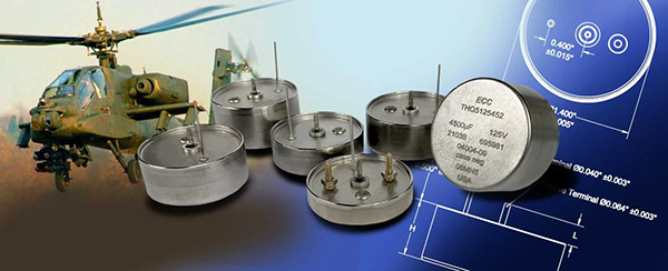
THQ series capacitors comes in a 1.4″ round case. They are available in 5 heights ranging from 0.312″ to 0.765″.
Electrical Specifications
|
Rated Voltage Range
|
10VDC to 125VDC
|
|
Capacitance Range
|
1,100uF to 200,000uF
|
|
Life (@85ºC)
|
>2000 hours @ Rated Voltage
|
Mechanical Specifications
|
Test
|
Method
|
Condition
|
Remarks
|
|
Shock
|
MIL-STD-202 METHOD 213
|
G
|
Tested for 11ms at 50g
|
|
Vibration
|
MIL-STD-202 METHOD 204
MIL-STD-202 METHOD 214
|
D
II, Letter E
|
12 sweeps/axis, 20g peak
1.5 hours/axis, 19.64g peak
|
|
Moisture Resistance
|
MIL-STD-202 METHOD 106
|
|
6V Polarity
|
|
Solderability
|
To ANSI J-STD-002
|
|
Operating Temperature Range
|
-55ºC to +85ºC or 125ºC with voltage derating
|
|
Storage Temperature Range
|
-62ºC to +130ºC
|
Capacitor Life
THQ Series capacitors are rated for >2,000 hours at 85°C and rated voltage or 125°C at de-rated voltage. The effective life of a capacitor in a given application is based on the specific operating voltage and average temperature. The rule of thumb says that every 10°C decrease in operating temperature yields approximately 2x the life. Additionally, each 10% de-rate in voltage will yield approximately 2x the life.
THQ Series Capacitors have an unlimited Shelf life.
Handling Guidelines
Attachment / Mounting by leads only is discouraged in applications exposed to mechanical shock or vibration. Always ensure capacitor is firmly secured to PWB, by either mounting studs, epoxy staking or both (preferred for vibration environments)
Provide adequate care to protect the Glass to Metal Seal (GTMS)
- Avoid forces on the positive terminal, lateral, axial or torque.
- Avoid mechanical shock to the positive terminal.
- Secure the part to PWB before soldering
Mounting with studs
- #2-56 CDA-752 studs available as a standard option.
- Use spacers (provided) to fill the gap between PWB and leaded surface of capacitor.
- Tighten Studs to 30-40 in-oz.
- Secure nuts (Stainless steel nuts provided) with Red Loctite, Do not use Lock washers.
Potting / Epoxy Staking
- We advise epoxy staking capacitor to PWB even when using studs, for maximum vibration tolerance
- In some applications it may be advisable to pot the cavity between the PWB and leaded surface
- Highest Shock/Vibration applications may require the capacitor to be fully potted.
Soldering
- Rim of Capacitor is intended to mate directly to PWB. Advise using no-clean flux.
- Utilize ANSI J-STD 001 Standard Through Hole Soldering methods.
Lead trimming
- Provide adequate care if leads must be trimmed
- Trimming the positive terminal is not recommended.
- Lead lengths available in 1/32″ increments from 0.125″ when measured from the rim of the capacitor