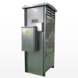
Dynamic Braking Resistors

Dynamic braking resistors are used on AC variable frequency drives (VFD's) to dissipate energy that is produced in the motor as the drive provides braking torque to stop the motor. The dynamic braking resistor is connected to the DC bus and will see voltages as high as 800 volts during braking conditions.
A three-phase variable frequency drive (VFD) consists of three basic components- rectifier, DC line, and inverter-and a control system to manage these three components. The rectifier converts the three-phase 50Hz AC input to a DC signal. Depending on the system, an inductor, a capacitor, or combination of these components smoothes the DC signal in the DC link part of the VFD. The inverter circuit converts the DC signal into a variable frequency AC voltage to control the speed of the motor.
When an overhauling or decelerating load on a motor causes the motor to turn faster than the synchronous speed set by a drive, the motor acts as a generator and transforms mechanical energy from the motor shaft into electrical energy. This AC power from the motor flows backward into the drive and causes the DC bus voltage to increase. Unless this regenerative energy is dissipated, once the DC bus voltage reaches a certain value, the drive will trip on bus overvoltage in order to protect itself. Dynamic braking is often the simplest and most cost effective means to dissipate the regenerative energy, thus allowing the drive to safely brake the load.
The rate of braking is dictated by how fast the energy can be put into the resistor, which in turn is determined by the ohmic value of the resistor. Each drive manufacturer specifies a resistance range with a minimum to prevent over current and damage to the drive and a maximum value to give adequate power dissipation capability for the application.
The peak braking current is a function of the drive chopper turn on voltage and the specified ohmic value.
The drive manufacturer normally determines the power rating (watts) needed to prevent overheating during braking duty. When the stop time is short in relation to the total duty cycle we may also need to consider the thermal capacity of the resistor, to ensure that it does not overheat during a single stop. In this case we will also need the absolute time on / time off in seconds.
Initial information needed for sizing your resistor:
- Duty Cycle (either a percentage or absolute time on / time off in seconds)
Standard Dynamic Braking Resistors
The Fortress standard range of braking resistors is available on short lead times. The enclosures are made of galvanized steel as standard and are also available in stainless steel. Ingress protection is IP 20 with an option for IP21 and IP23. A terminal box and thermostat are standard.
Custom Dynamic Braking Resistors
Fortress specialise in customer designed dynamic braking resistors for the mining industry. In particular we are able to supply a range of resistors mounted in GR316 stainless steel cyclone rated enclosures that come equipped with an IP56 terminal box including all of the features expected on an Australia mine site. The resistors have been proven on conveyors, stackers, and reclaimers at dry and dusty sites in the Pilbara and in marine environments on shiploaders all around Australia.